Welcome to my first-ever ArtStation blog post! I will break down how I made procedural ceiling tiles that react to wind.
First, we will explore how I built the system for procedurally generating the ceiling. We will then break down how the wind system I designed, works but not before examining how each ceiling tile reacts to the forces created by the wind system.
If you have not seen the demo video already, you can watch it right here on ArtStation.
Now that you've seen the video, let's take a peek under the hood!
Tile Grid Generation

I started this system by creating the blueprint responsible for generating the ceiling. Since ceiling tiles like those found in offices are arranged in a grid-like fashion, the first order of business was to simply generate a grid with each point containing information about what to spawn. To accomplish this, I created a map variable that stores the grid coordinates in integer form as a key and then a structure containing all the properties of the tile as its corresponding value.

Tile Info Struct

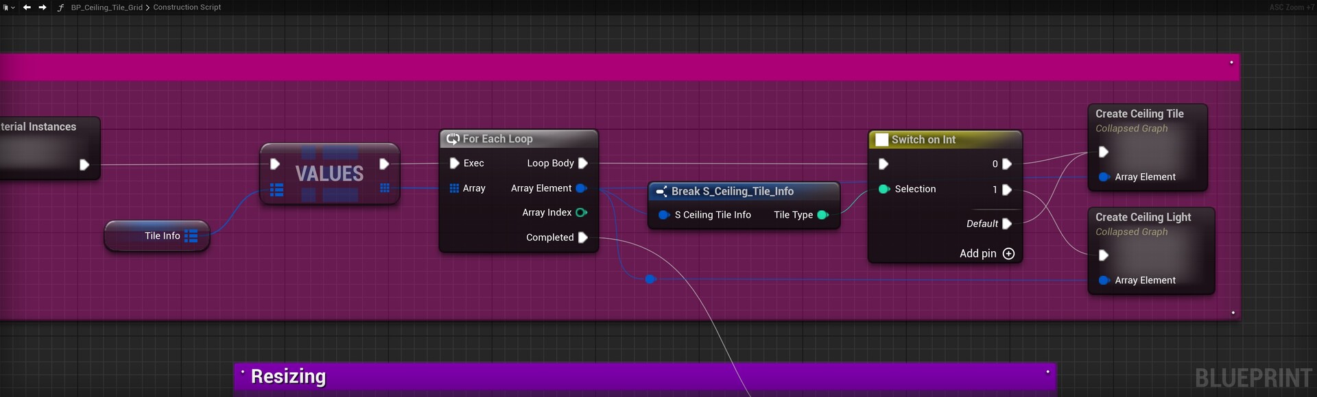
tileType: allows us to choose what to generate on the grid tile. 0 = ceiling tile, 1 = fluorescent light. Of course, this opens the tile generator to new possibilities regarding ceiling customisation.
gridCoordinates: The coordinates of the tile
susceptibleToWind: Flags whether to respond to the wind system. I forgot I added this and is completely ignored by the tiles and the wind system. This would be easy, however, to add in later on.
transform: The transform of the mesh to be spawned. I did not need the rotation and scale components of the transform but it's nice to have them just in case.
Light Panel Alternation

You may have noticed a collapsed set of nodes called Light Panel Alternation. The contents of this are not important. All you need to know is that it's a set of nodes that make the ceiling tile grid blueprint alternate between generating fluorescent light panels and ceiling tiles. This is what enables the functionality of the Light Grid property.

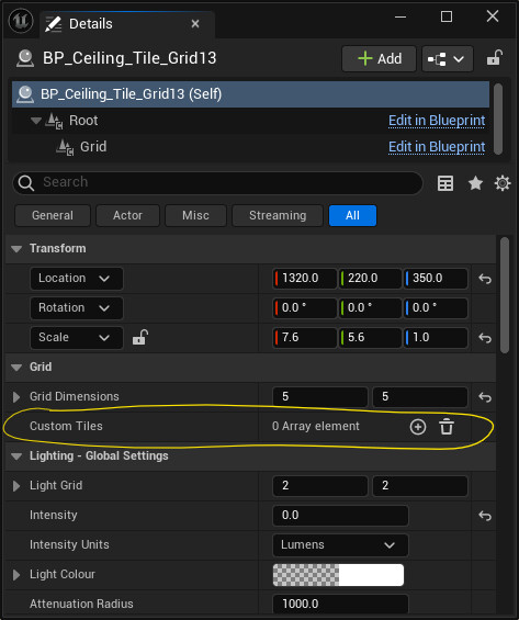
Custom Tiles
The next step in the grid generation process is to generate the custom tiles. This is what enables the custom tiles settings in the properties panel.
For every custom tile entry in the list, I am replacing the existing tile information for said tile, with the custom information provided by the artist. Essentially, we want to override the properties of an existing tile, which is the reason for being the second step in the grid generation process.

The only thing left to do now, is to generate either a ceiling tile or a fluorescent light, depending on the tile ID of each tile:
Tile Resizing
One of the most important (and one of my favourite) aspects of this system is how easy it is to scale the ceiling. In the demo video, you would've seen me stretch out an entire ceiling tile to fill in the ceiling and then divide it into a grid of tiles. Here is how I achieved it:

Before the construction script executes, the blueprint starts with two scene components: Root and Grid. When tiles, fluorescent lights or any other custom tile spawns, it gets attached to the grid component.

Afterwards, the blueprint resizes the grid's relative scale so that it's inversely proportional to the number of grid tiles in each dimension.
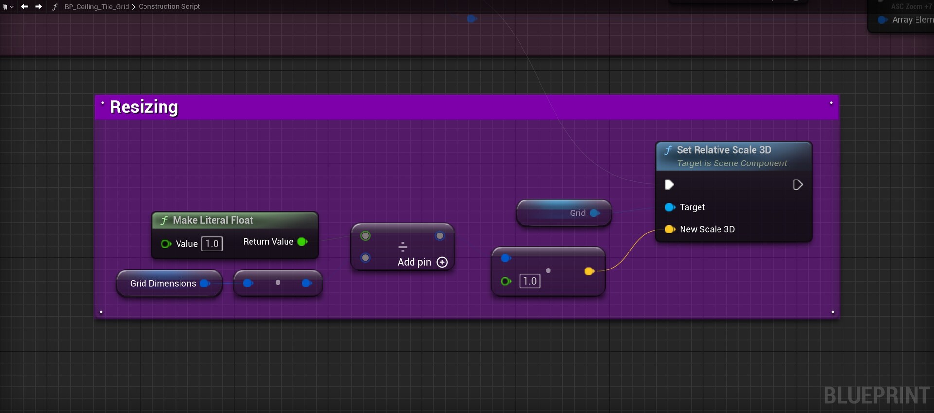
The artist can then scale the Root component (or the entire actor) to whatever they like and the grid will always scale correctly.
Materials & Textures
The ceiling tile mesh uses a simple material setup. It is using the base material the rest of my project is using. It has Texture2D parameters for the necessary texture maps.

There was one problem with this material setup: It relied on UV texture coordinates that didn't scale according to the scale of the tile. This is where the MF_World_Aligned_Scaling node comes in:

This custom material function I made gets plugged into a UV input on a texture sample. At a superficial level, it functions quite similarly to world-aligned coordinates. The difference is that it only affects the scale of the texture. World positioning and rotations are unaccounted for. I wanted to have this to eliminate the inevitable texture stretching that comes with dividing a grid into a non-square arrangement.
That just about wraps up everything you need to know about how the ceiling tile grid works. Let's move on to how the tiles react to wind!
Wind
I'm going to start by giving a high-level overview of how the wind system works.
- We take a wind emitter and place it near a tile.
- The wind emitter tells the ceiling tile that the tile is within its radius. The ceiling tile, then, calculates the wind direction and strength. If the ceiling tile is within the radius of multiple wind emitters simultaneously, the wind calculation is performed for all the neighbouring emitters and the results are added together.
- The final wind calculation gets passed on to the ceiling tile's animation blueprint, where it decides how much lift the tile should have and in which direction.
Let's look at this process more in-depth.
BP_CeilingTile_WindEmitter

The wind emitter blueprint lets us control various aspects such as the radius, falloff and speed (for when the emitter is moving). Apart from this, it doesn't do much else. All it does is look out for ceiling tiles using the OnComponentBeginOverlap and EndOverlap events. This is great because it means it doesn't need to use the Event Tick function for anything.
OnComponentBeginOverlap: When a ceiling tile enters the radius of the emitter, the emitter will call the Register Wind Force function. The ceiling tile will add the emitter to a map stored in the tile blueprint, along with its radius. The radius will be used in the wind calculation later.


Wind Calculation
At any given moment during runtime, all ceiling tiles are calculating wind velocities if their currentWindForces map is populated. If their maps are empty, a reset event will trigger in the tile's animation blueprint. This is to ensure the tile remains closed when no wind forces are acting upon it.

For each wind force, we are calculating the wind velocity and then multiplying it by a factor based on how large the radius of the wind force is compared to its neighbouring wind forces. This is so that the larger and more global wind forces have a stronger influence on the tile, compared to the smaller and more localised wind forces. I assumed that wind forces with large radii were like big gusts of wind compared to those with small radii, which were more like pockets of wind.

For this calculation, we need to know the world location of the wind emitter. We also need to know where the centre of the tile is in world space. I did not use a GetActorLocation function for this because the origin of the ceiling tile is placed at a corner of the tile. Instead, I used the origin of the component's bounds. We also need to know the radius of the wind emitter.

At this point, we now need to calculate the strength of the wind in each direction. I calculated this on a per-axis basis because the calculation for the z-axis is a bit different. The simple way to calculate this would be to take the distance between the wind origin and the tile origin and call it a day. This was initially how the calculation was done but I thought it could be a little more accurate if I did it a slightly different way.

Instead, we calculate the wind strength as we normally would for the x and y axes. Working out how close to the centre of the wind emitter the tile is and also applying a falloff curve to it. We then use the vertical distance between the tile and the emitter as a weighting factor to further control the strength. The result is multiplied by the direction of the wind emitter relative to the tile.

The final result of these calculations is clamped so that it remains between -1 and 1 and then added to the final wind velocity. The Apply Wind event is called in the animation blueprint and the velocity value is passed to it.

Animation Blueprint
The animation blueprint for the ceiling tiles controls how much lift a tile has. I've added several effects that enhance the movement of the tile. The first effect is the initial 'Open Amount'. This is controlled by the wind velocity value being fed to the blueprint. The next effect is called 'Centre Lift'. This is a more subtle effect but it controls how much lift the entire tile has. Essentially, I wanted the entire tile to lift off its railing slightly when affected by the wind. After this effect, the next one is the jitter value. This makes the tile flap up and down to the wind. The last effect, and my favourite one of them all, is the interpolation effect. This one applies to the initial open amount and the centre lift effects. It makes the tiles react to the wind gradually, rather than instantly.
The Blend Space Asset

The blend space accepts values between -1 and 1, where -1 = Open in the south/west directions, 0 = closed and 1 = open in the north/east directions.
In the Animation Graph, we are supplying the currentOpenAmount vector to the blend space to control the lift of the tile.

This is also where the jitter effect is applied.
Initial Open Amount

The initial open amount works by simply setting the Target Open Amount to the wind velocity. You might wonder why there are now two 'open amount' variables. In fact, there are actually three variables that play a role in controlling the open amount. This is related to the interpolation effect. If we want to set the amount of lift for the tile, we set the Target Open Amount.

Centre Lift
The next step is to calculate the Target Centre Lift value. We feed the Target Centre Lift vector the Z-value of the wind velocity vector, which contains the vertical distance between the wind emitter and the tile. The effect is applied after the blend space value is set in the Animation Graph.

Jitter Value
The jitter value gets added to the open amount value being supplied to the blend space.

The value is calculated on every animation update, using a trigonometric expression and evaluated using the game's delta time. The time variable merely adds a random offset to the delta time that varies the 'jittery-ness' across all the tiles. This random offset is set when the game starts.
Value Interpolation
The last effect for the tile animation revolves around the time-based interpolation of the 'Open Amount' and 'Centre Lift' values. There are two components to this: The final interp speed and the previous, current and target values.
I wanted to have a fast and instantaneous interp speed for when the tile lifted upwards from being thrust by the wind and another, more slow and gradual interp speed for when the tile floated gently back down.
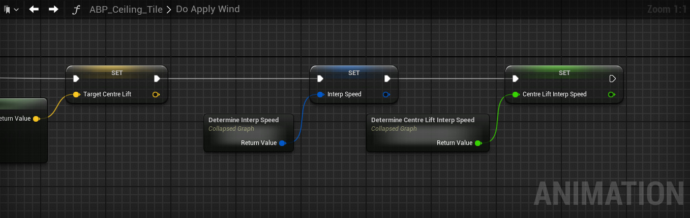
To work out which interp speed to use, we need to work out which direction (up/down) the tile is moving in by comparing the previous and current open amounts (or Centre Lift).

Reducing the outcome to a single negative or positive sign will tell us which direction the tile is going in and thus, the corresponding interp speed is selected.
The next component of the interpolation happens in this set of nodes here:

We are leveraging the Blueprint Update Animation event to drive these interpolations. At the beginning of each update, we are setting the 'previous' values so that the interp speeds can be determined. Then, we are performing the interpolations inside the collapsed set of nodes on the right.

We are making extensive use of UE5's built-in FInterp To and VInterp To functions. Setting the 'target' values for the effects will make the tile interpolate to that position over time. This is why the Apply Wind function sets the target open amount to the wind velocity it has been fed, instead of the current open amount. The same rule applies to the target centre lift value.
That wraps it up for how the wind system works. Let us now take a quick look at wind volumes, which extend upon the functionality of the wind emitters.
Wind Volumes
While wind emitters can be used in isolation, they can also be spawned using Wind Volumes. A wind volume spawns wind emitters somewhere within a defined boundary. I created two classes for wind volumes: the base class BP_Wind_Volume and a child class BP_WindPocket_Volume. Let's look at both of these classes.
BP_Wind_Volume

This is the base class for all wind volumes. At the same time, this particular volume spawns wind emitters from the edge of the volume and shoots them to the opposite end of the volume.

While the functionality of this volume works fine, there seems to be an issue with tiles not reacting properly to the moving wind emitters. It could be something to do with the wind emitters moving via their Interp To movement components but I decided not to solve this problem because I felt that the subclass BP_PocketWind_Volume was better suited to the environment I'm building.
Despite the lack of plans to use this volume type, let's look at how it functions.
Component Hierarchy
The component hierarchy for all wind volumes includes a trigger box for defining the bounds of the volume. They also include what I call a HelperSphere. This is a "fake" wind emitter (it's really just a sphere collision component). This is meant to help the artist preview how big the radii of the wind emitters will be. There is also an arrow to indicate the direction the wind emitters will move in.

Modes
The volumes can operate in two modes: Continuous and On Demand. Continuous mode makes the volume spawn emitters on a timer while respecting the emitter limit. On Demand mode lets the artist spawn the emitters themselves.

Continuous Mode
In continuous mode, the volume starts by assigning the SpawnEmitterContinuous event to a timer.

The event triggers periodically and calls the SpawnEmitter function.

On Demand Mode
The volume does nothing in On Demand mode until something calls the SpawnEmitter function. It does, however, stop the timer that triggers the SpawnEmitterContinuous event if it was previously set.

Spawning the Emitters
Spawning the emitters occurs via the SpawnEmitters function:

This function is overridden in child classes like the BP_WindPocket_Volume class so that the spawn functionality can be augmented to the class' needs. When spawning an emitter, the artist has the option of using the emitter properties supplied by the volume itself or custom properties can be used.

Once we've chosen which set of properties to use, this particular class will spawn an emitter and shoot it in a specific direction.

Wind emitters have an Interp To Movement Component. The component moves the wind emitter based on a set of key points. In our case, we need only two key points: A start and end point. These points are calculated using a custom function I wrote that gets the closest point on the surface of a box, given a direction. The start point will be the closest point on the WindBox's surface in the opposite direction of the wind. The endpoint will be the closest point in the direction of the wind.

The volume spawns a wind emitter and supplies its movement component with the start and end points. At this point, the wind emitter will simply take off in its calculated direction. Once the emitter reaches its destination, it will destroy itself if its destroyOnPathCompletion flag is set. The volume also assigns its OnEmitterDestroyed event to the emitter's OnDestroyed event to know when to decrement the emitter counter.

This wraps up how the BP_Wind_Volume class works. Let's look at its child class BP_WindPocket_Volume.
BP_WindPocket_Volume

This subclass of the BP_Wind_Volume class does not differ much from its parent. The only difference is that the SpawnEmitter function is overridden to spawn emitters in a slightly different way.

We can still choose whether to use custom properties but rather than calculating surface points from directions, we are simply generating a random point inside the box. The result is emitters that spawn in random locations inside the volume.
This volume also comes with the added ability to control the lifespan of the emitters. It simply sets the actor's lifespan to a random duration between 0.5 and 10 seconds.
Wrapping Up
This brings us to the end of this breakdown. A lot is going on in this system and it is one of the most complex systems I have made in Unreal Engine to date. Most importantly though, I had a lot of fun building it.
Of course, with everything you make as an artist, there is always room for improvement. The biggest improvement I would make would either have to be writing these systems in C++ rather than a blueprint or using something like Houdini. During the writing of this blog post, I discovered that Houdini would've probably been a better solution to go with since its workflow is all about procedurally-generated content. It also has a plug-in for UE5. Perhaps it's time for me to learn Houdini!
If you have made it this far, thank you so much for reading. I hope you found this useful and that you take away something handy to try in your projects. If you have any questions about this breakdown, feel free to message me.
See you next time!